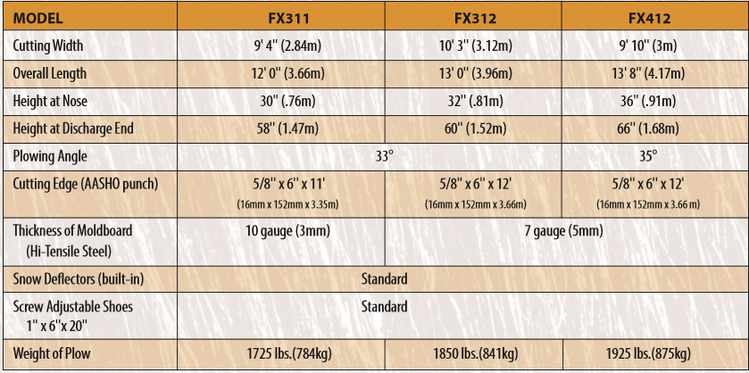
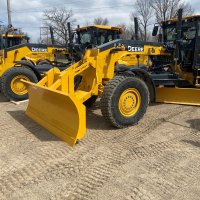
One Way Snow Plow
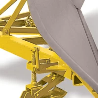
Rigid and trip blade units for use at all operating speeds. Recommended for municipal use on: airports, highways, city streets and rural roads. For use on trucks, motor graders and wheel loaders.


Features
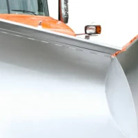
- Smooth rolled moldboard for a clean lift, roll, and throw of snow.
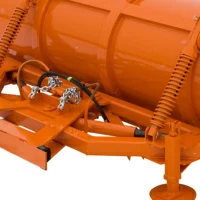
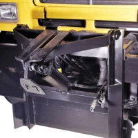
- Screw-adjustable oscillating shoes are standard.
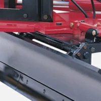
- Rigid tilting bars are standard.
- 7 Gauge Moldboard
- Rolled Heavy Channel Ribs


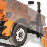
Specifications