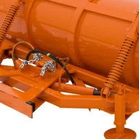
Rox Snow Plow
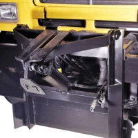
Trip Moldboard and Slotted Trip units for use at all operating speeds. Recommended for airports, highways, city streets, and rural roads.


Features
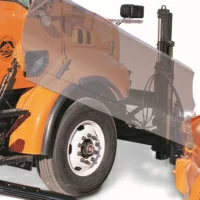
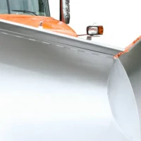
- Lower left side for improved driver visibility and safety
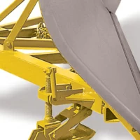
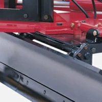
- Five heavy rolled channel ribs, horizontal braces for enhanced moldboard reinforcement
- Precise moldboard curvature provides lift, roll, and throw of snow for maximum efficiency


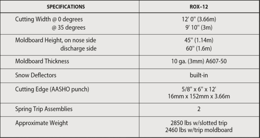
Specifications